


Crystal Oscillators' Output Wave
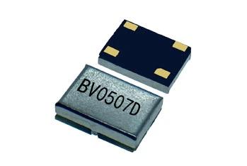
Crystal Oscillator Output Waveforms Explained: CMOS, LVCMOS, LVDS, LVPECL, CML, Sinewave, and More
Understanding Crystal Oscillator Output Waveforms
Crystal oscillators are essential timing components in electronic systems, but frequency accuracy is only one part of proper oscillator selection. Engineers must also choose the right output waveform or output logic type for the circuit. The output format determines how the oscillator communicates with the receiving device, how much power it consumes, how fast it switches, how much noise it creates, and how it should be terminated on the PCB.
Common crystal oscillator output types include CMOS, HCMOS, LVCMOS, TTL, sinewave, clipped sinewave, PECL, LVPECL, LVDS, and CML. Each has different voltage levels, drive capability, signal swing, jitter performance, and layout requirements.
Choosing the wrong oscillator output can cause signal integrity problems, excessive current consumption, timing errors, poor noise performance, or even device incompatibility. Choosing the right output helps improve clock reliability, reduce electromagnetic interference, and simplify system design.
Why Oscillator Output Type Matters
Every oscillator output must match the electrical requirements of the receiving circuit. A microcontroller may need an LVCMOS clock. A high-speed communication chipset may require LVDS or LVPECL. An RF system may prefer a sinewave output because of its spectral purity. A legacy digital circuit may use TTL.
The output waveform affects key design factors, including:
Supply voltage compatibility
Logic threshold compatibility
Rise and fall time
Jitter and phase noise performance
Power consumption
Electromagnetic interference
PCB routing method
Termination requirements
Maximum usable frequency
Signal integrity over distance
For modern high-speed systems, engineers must evaluate both the oscillator specification and the receiving device input standard.
CMOS Crystal Oscillator Output
CMOS, or Complementary Metal-Oxide-Semiconductor, is one of the most common output types for crystal oscillators. A CMOS oscillator produces a square wave that switches between low and high logic levels, typically from ground to the supply voltage.
For example, a 3.3V CMOS oscillator usually outputs a signal that swings close to V and 3.3V. This makes it easy to connect directly to digital ICs such as microcontrollers, processors, FPGAs, and clock inputs.
Advantages of CMOS Output
CMOS output offers several benefits:
Simple interface with digital logic
Full rail-to-rail voltage swing
Low static power consumption
Widely available in many frequencies
Easy PCB implementation
Suitable for embedded systems and general digital circuits
Limitations of CMOS Output
CMOS is not always ideal for very high-speed clock distribution. Its large voltage swing can create higher EMI, and fast edges can cause ringing if traces are not designed properly. CMOS outputs also become more difficult to distribute across long PCB traces or multiple loads.
CMOS oscillators are best for short-distance clock routing and moderate-frequency applications.
HCMOS Oscillator Output
HCMOS stands for High-Speed CMOS. It is a faster version of traditional CMOS and supports sharper transitions and improved switching speed. In many oscillator datasheets, the terms CMOS and HCMOS are sometimes used interchangeably, especially when referring to square-wave oscillator outputs.
HCMOS is useful when a design needs CMOS-compatible voltage levels with faster edge rates. However, because faster edges can increase EMI and signal reflection, engineers should pay close attention to PCB layout and termination.
LVCMOS Oscillator Output
LVCMOS means Low Voltage CMOS. As the name suggests, LVCMOS operates at lower supply voltages such as 1.8V, 2.5V, or 3.3V. It is widely used in modern digital electronics because many ICs now operate from low-voltage power rails.
Benefits of LVCMOS Output
LVCMOS provides:
Lower power consumption than higher-voltage CMOS
Compatibility with modern low-voltage ICs
Reduced switching noise
Good performance for compact embedded designs
Easy connection to processors, FPGAs, ASICs, and microcontrollers
LVCMOS crystal oscillators are common in IoT devices, portable instruments, communication modules, consumer electronics, and industrial control systems.
ACMOS Oscillator Output
ACMOS stands for Advanced CMOS. It is another CMOS family designed for improved speed and performance. While less commonly discussed than CMOS, HCMOS, or LVCMOS in oscillator selection, ACMOS may appear in some timing products and digital logic specifications.
Designers should check the datasheet voltage levels, load drive, rise/fall time, and input compatibility before selecting ACMOS-based timing devices.
TTL Crystal Oscillator Output
TTL, or Transistor-Transistor Logic, is an older digital logic standard. TTL oscillator outputs typically use a 5V supply, but the logic high level does not necessarily swing all the way to 5V. TTL was widely used in legacy digital circuits, industrial controls, older processors, and traditional test equipment.
Advantages of TTL Output
TTL outputs are useful in systems that still require legacy logic compatibility. They offer clear logic thresholds and robust switching for older designs.
Limitations of TTL Output
Compared with CMOS and LVCMOS, TTL usually consumes more power and is less common in new low-voltage designs. Many modern ICs no longer support 5V TTL inputs directly, so level shifting may be required.
TTL oscillators are mainly selected for replacement, maintenance, or compatibility with older electronic systems.
Sinewave Crystal Oscillator Output
A sinewave oscillator output produces a smooth analog waveform rather than a digital square wave. This output type is often used in RF, microwave, communication, and test applications where spectral purity matters.
Sinewave outputs typically offer better harmonic performance than square-wave outputs. Because a square wave contains many harmonics, it can generate more EMI and unwanted frequency content. A sinewave signal is cleaner and more suitable for frequency reference applications.
Common Applications of Sinewave Oscillators
Sinewave crystal oscillators are used in:
RF systems
Frequency synthesizers
Signal generators
Spectrum analyzers
Communication equipment
Radar systems
Laboratory reference clocks
Low phase noise applications
Sinewave outputs usually require impedance matching, often to 50 ohms, depending on the circuit.
Clipped Sinewave Oscillator Output
A clipped sinewave output is a low-amplitude waveform that resembles a sinewave with flattened peaks. It is commonly used in low-power TCXO and RTC applications.
Clipped sinewave outputs consume less power than full CMOS outputs because they use a smaller voltage swing. This makes them ideal for battery-powered devices where energy efficiency matters.
Benefits of Clipped Sinewave Output
Clipped sinewave oscillators provide:
Very low power consumption
Reduced EMI compared with square-wave outputs
Suitable output for RTC and timing IC inputs
Good choice for portable and battery-powered systems
Design Considerations
A clipped sinewave output may not directly drive standard digital logic inputs unless the receiving IC is designed for it. Engineers should verify input sensitivity and biasing requirements before use.
PECL Oscillator Output
PECL stands for Positive Emitter-Coupled Logic. It is a high-speed differential logic standard derived from ECL technology but referenced to a positive supply voltage.
PECL outputs provide fast switching and excellent high-frequency performance. Because they use differential signaling, they offer better noise immunity than single-ended CMOS or TTL outputs.
However, traditional PECL often uses a 5V supply and consumes more power than lower-voltage standards. It also requires proper termination for reliable operation.
LVPECL Oscillator Output
LVPECL, or Low Voltage Positive Emitter-Coupled Logic, is a lower-voltage version of PECL. It is widely used in high-speed clock distribution, telecom systems, optical modules, and data communication equipment.
LVPECL outputs typically provide large differential signal swings and excellent jitter performance. This makes them suitable for demanding high-frequency timing applications.
Advantages of LVPECL Output
LVPECL offers:
Very fast switching speed
Low jitter performance
Strong noise immunity
Good signal integrity at high frequencies
Suitability for telecom and networking systems
LVPECL Termination
LVPECL usually requires termination to a voltage below the supply rail, often through resistor networks. Incorrect termination can cause poor waveform quality, excessive power consumption, or clock instability. Designers should always follow both the oscillator datasheet and receiver input recommendations.
LVDS Oscillator Output
LVDS, or Low Voltage Differential Signaling, is a popular differential output type for high-speed, low-power systems. LVDS uses a small differential voltage swing, commonly around 350 mV, which reduces power consumption and EMI.
LVDS is widely used in applications where clean timing and efficient operation are important.
Advantages of LVDS Output
LVDS provides:
Low power consumption
Low electromagnetic interference
Good common-mode noise rejection
Reliable high-speed performance
Excellent suitability for differential PCB routing
Common LVDS Applications
LVDS crystal oscillators are common in:
Servers
Routers and switches
Optical modules
Video systems
Telecom equipment
Data converters
FPGAs and high-speed digital systems
LVDS Termination
LVDS usually requires a 100-ohm differential termination resistor placed close to the receiver input. Proper differential routing and impedance control help preserve signal quality.
CML Oscillator Output
CML, or Current Mode Logic, is another high-speed differential output standard. It is often used in very high-speed serial communication systems, transceivers, and clock distribution networks.
CML outputs typically provide fast transitions, controlled current switching, and excellent performance at high frequencies. They are commonly used in advanced communication interfaces and high-speed data paths.
Advantages of CML Output
CML offers:
Excellent high-speed capability
Good signal integrity
Low voltage swing options
Compatibility with high-speed transceivers
Strong performance in serial data systems
CML termination varies depending on the device architecture, so designers must carefully follow datasheet guidance.
Single-Ended vs Differential Oscillator Outputs
Oscillator outputs can be divided into two broad categories: single-ended and differential.
Single-Ended Outputs
Single-ended outputs use one signal line and a ground reference. Examples include:
CMOS
HCMOS
LVCMOS
TTL
Sinewave
Clipped sinewave
Single-ended outputs are simple and cost-effective, but they are more sensitive to ground noise and EMI.
Differential Outputs
Differential outputs use two complementary signal lines. Examples include:
PECL
LVPECL
LVDS
CML
Differential outputs provide better noise rejection, lower EMI, and stronger high-speed signal integrity. They are preferred for fast data systems, communication equipment, and precision clock distribution.
Matching Output Waveform with Supply Voltage
Different oscillator output types require appropriate supply voltages. For example, LVCMOS may operate at 1.8V, 2.5V, or 3.3V, while TTL and PECL may require 5V in some designs. LVDS and LVPECL often operate from 2.5V or 3.3V depending on the product.
Supply voltage affects:
Output amplitude
Logic compatibility
Power consumption
Jitter performance
EMI behavior
Receiver input margin
Before selecting an oscillator, engineers should confirm that the oscillator supply voltage, output waveform, and receiving IC input standard are compatible.
How to Choose the Right Crystal Oscillator Output
To select the best oscillator output type, consider these factors:
Required frequency
Receiver input standard
Supply voltage available
Power consumption limit
Jitter and phase noise requirements
PCB trace length
EMI requirements
Single-ended or differential routing
Termination method
System operating environment
For microcontrollers and embedded systems, LVCMOS is often the simplest choice. For RF references, sinewave may be preferred. For high-speed networking, LVDS, LVPECL, or CML may provide better performance.
Conclusion: The Right Output Waveform Improves System Performance
Crystal oscillator output waveform selection plays a major role in electronic design. CMOS, HCMOS, LVCMOS, TTL, sinewave, clipped sinewave, PECL, LVPECL, LVDS, and CML each serve different applications.
Single-ended outputs are simple and practical for many digital systems. Differential outputs provide superior performance for high-speed and noise-sensitive designs. Analog sinewave options support RF and precision frequency applications, while clipped sinewave outputs help reduce power consumption in portable devices.
By matching the oscillator output type with the correct supply voltage, receiver input, PCB layout, and termination method, engineers can build more stable, efficient, and reliable electronic systems.
If you want to know more about hcmos vs cmos, please visit our website.
Xtaltq Technologies Co., Ltd was founded in 2009 and located in Chengdu, China. We have 800 square meters of production workshop in Shuangliu District, Chengdu, with high-precision fully automated placement machine, automatic test system, phase noise meter, etc. Our main products contains TCXO, 0CX0, VCX0 etc. We are in the leading position in the industry/military grade and work with many famous enterprises overseas.

 English
 French
 Spanish
 Portuguese
 Deutsch
 Turkish
 Dutch
Dutch
 Italiano
 Russian
 Romaian
 Portuguese (Brazil)
 Greek
Greek